Increasing Test Coverage In Hard Switching Half Bridge Configurations
Hard switching in half bridge configurations is a common place technique for efficient power conversion at high power levels .
With increasing switching speeds as in SiC designs, parasitic coupling from the switch node to the gate is becoming more and more critical, with shoot-through conditions that can destroy the transistors; hence it is important to make sure there are no critical glitches on the high side gate of the half bridge.

The R&S®RTO and R&S®MXO oscilloscopes offer an advanced, easy-to-use digital trigger unit with:
►High flex ibility in setting up complete real-time A/B/R trigger conditions
►Individual setting of the trigger hysteresis to optimize the trigger sensitivity for the respective signal
►High trigger sensitivity at full bandwidth to capture small, unwanted glitches
►Very low jitter values for stable triggering
When adjusting the trigger value for the high side gate signal to the largest acceptable value, users can easily identify any switching event that violates this condition.
Operating the DUT at different load and environmental conditions during verification tests makes it possible to identify critical conditions and eliminate the risk of a shoot through.
This task requires a complex trigger setup and very high trigger accuracy, and the trigger threshold must be precisely defined.
After connecting the oscilloscope to the DUT, the user configures all relevant trigger options .
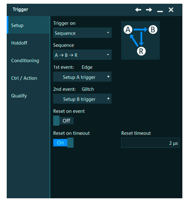
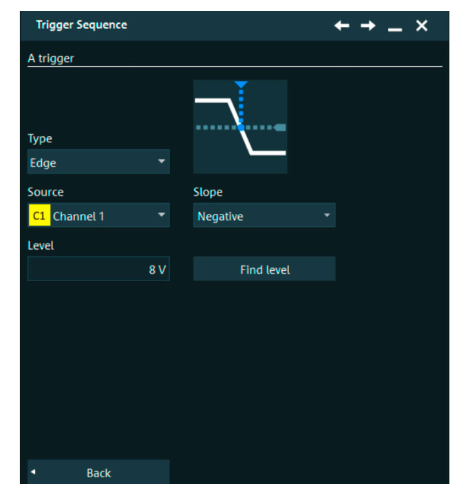
►Select the trigger sequence to define two events in a sequence (fig. 1 and 2) Define the first trigger event (A ) as a negative edge trigger to catch the falling edge of the Vgs at switch T2. This trigger event will catch every switch-off event of the low side switching device during continuous operation of the half bridge.
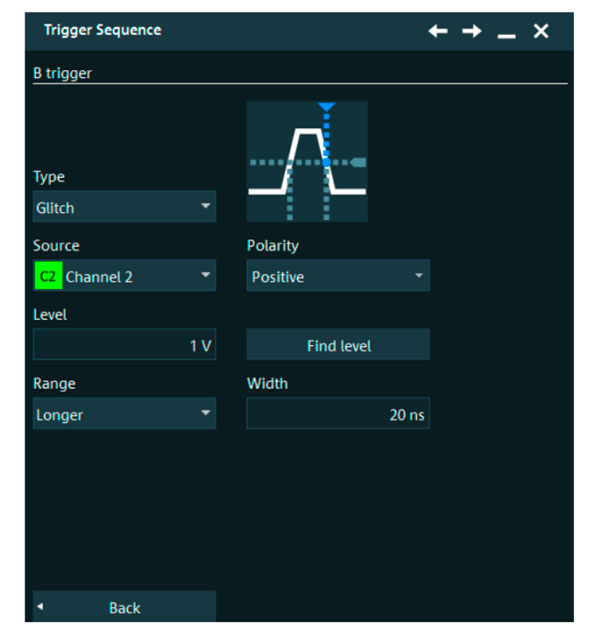
►Define the nex t trigger event (B) to detect a glitch on the gate to source terminal on switch T1. This trigger is only active after the first trigger event (A ) has occurred.
►Define as reset condition to reset the trigger after a specific timeout the max imum on-time of the low side (fig. 3)
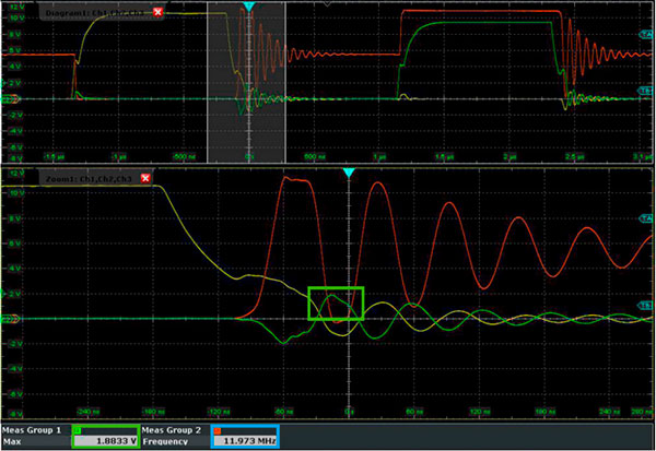
Application measurement results (fig.4)
A 500 W half bridge DC/DC converter is used to demonstrate how to automatically identify critical gate timing events that can lead to a shoot through. Input voltage between 36 V and 72 V generates an output voltage of 3.3 V. The switching frequency is 400 kHz .
According to the data sheet, the lowest possible threshold voltage of the MOS FE T gate is 2 V.
To identify the safety margin, reduce the trigger level for the high side gate glitch trigger starting at 2 V until a trigger event happens .
At 1.88 V (green box ) trigger events are generated as shown in the measurement result. This means a safety margin of 120 mV, depending on the actual application. In addition to the trigger capability, the user gains even more insight into the circuit, such as the resonance frequency (blue box ) between leakage inductance of the transformer and output capacitance of the switch.